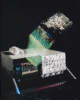
DataSYS 765 DRO
 |
Recording waveform detail over a period of hours where the unit under test is being monitored over varying temperatures, the waveform detail can be measured and graphed during replay to show variation in performance such as risetime, pulse width or input and output power. Automatically acquire waveforms for a defined time at preset or triggered intervals. This allows detailed waveform performance to be analyzed and toleranced at all periods of a life test without being permanently in attendance. Acquire waveforms during an engine start period and save for subsequent analysis. Run the recording slow but using the high speed glitch capture to find random spurious events. Using the replay function, accurate timing will give time of occurrence. |
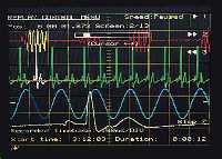 |
Flexibility in the way waveforms are captured and stored is a unique feature of the 765. DataSYS 765 has two distinct modes of operation - Digital Storage Oscilloscope and Recorder - both demonstrated on this screen. This unique combination gives the benefit of having all the performance of high speed digital storage with its associated live measurement and analysis functions. |
Recorder mode writes directly to hard disk or paper giving a very large memory with no breaks in the record. The high speed storage feature is utilized so that glitches are detected and recorded. Record a complete experiment for minutes or weeks and use the replay function at the same time, making measurements and analyzing the waveforms.
Markers are available to record points of interest. These points can be accessed instantly during replay using the 'Go to Marker' controls.
The display shows waveforms in Replay with softkey controls for forward and reverse. A Move control is operated by the cursor control with a display of screens and time into the recording. While in Replay, traces can be zoomed to show fine detail. During Replay, measurements can be made on the trace or the output recorded on paper. Graphs and histograms can also be performed during Replay.
|
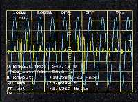
With modern switching techniques being extensively used throughout industry, it is important to measure the performance of switch mode supplies. The waveforms shown are acquired voltage and current with the calculated power waveform supplying a laser. The current is pulsed, producing a large number of harmonics. Custom Measurements are set up to measure live - over a precise number of cycles - the rms voltage, rms current, VA, real power and power factor. The measurements are performed to ensure standards are met for power loading. |
 |