Delta 9500A
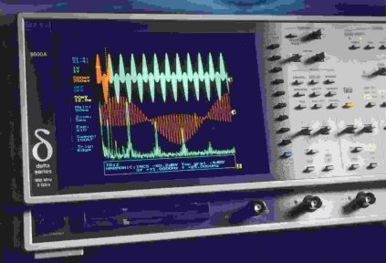 |
Delta 9500A applications include signal analysis, timing measurements and the important task of electronic troubleshooting. With 500 MHz bandwidth and 2 GS/s Sample Rate - coupled with high quality, low noise input amplifiers - users can be assured that captured waveforms are true. Trigger Tools have features that are ideal for locating information in TV lines or specific areas within data streams. Count and Divide, used in conjunction with Gating is extremely powerful when viewing complex digital signals in detail. In addition, a unique clock phase shift control allows users to step through a data stream, allowing the full acquisition performance to be used at each step. Single events such as too short a pulse (a spike or glitch), too small a pulse (runt or noise) or a floating signal (transition time or slew rate fault) can also be handled using Trigger Tools. |
In any Trigger Tool application, setting up the trigger condition is assisted by truly interactive icons and virtual LEDs. The icons change as setup selections are made within the Trigger Tools control menu. Delta 9500A icons are dynamic timing diagrams which genuinely help the user understand how a particular trigger mode is applied to the input signal. Live trigger indication is incorporated into the setup menus which clearly show the status of the Trigger Tool setup at any time, responding to the actual input signals.
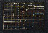 |
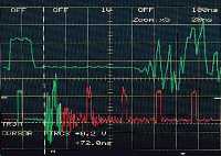
Uniform fast edge and low noise at all input sensitivities. This screen display shows both the exceptionally Low Noise of the Delta 9500A as well as the uniform pulse response regardless of input sensitivity. Low Noise is obviously desirable because, if a 'scope generates less noise itself, the displayed traces more faithfully represent the actual input signals. If there is noise on the trace it's there because the signal contains noise, and the user can begin to look for noise in his system with some confidence that it's actually being caused there, not in the 'scope. |
Uniformity of pulse response also has to do with signal fidelity, because a well behaved, fast pulse corner is indicative of low passband ripple and uniform bandwidth. This means that the general shape of pulse edges and corners will be consistent when timebase and input sensitivity ranges are changed.
Active Probes are available to achieve the full bandwidth, maintaining a high impedance input even down to 2 mV/div sensitivity.
|
Ansi. TI 102 Telecomms Testing Template is just one example. The limits testing facility within the Delta models checks an input waveform against both the upper and lower limit curve to determine if either has been exceeded. Telecomms Testing is an ideal application area for the Delta 9500A because of its 500 MHz bandwidth, uniform pulse response, and Low Noise. In addition, standard pulse limit templates have been developed as part of the Application Disk (3.5" diskette) supplied with each instrument. Gould Transition2 is a Microsoft Windows® software application which allows easy transfer of data from a Delta to a PC, via either IEEE-488.2 or RS-423. |
 |
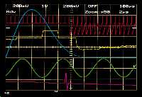 |
Showing several options at once to highlight the Delta 9500A's flexibility. The Main & Zoom facility presents waveforms live showing the complete acquisition and full detail |
|
Triggering on each Nth event. Divide by N gives a stable display of PAL TV waveform. A large number of difficult trigger conditions are catered for in the Delta 9500A. These include:
|
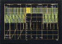 |
The screen display shows video synchronized to the frame with the "main" trace captured at 500 µs/div, and simultaneously the expanded "zoom" (×10) trace shows the field sync pulses at 50 µs/div. It is important to note that the Zoom trace obviously appears to be expanded when compared to the main trace, but in fact both traces contain only real data points, joined with vertical line segments. If the 50,000 word store length has been selected, the Zoom trace can be expanded relative to the main by a factor of up to 1000. With 200 kbyte or 1 Mbyte memory options, the Zoom expansion is up to ×4000.
Divide by N triggering has been used with the divide factor set to 640 - the number of line sync pulses in the complete frame. Many DSOs offer Delay by N events, but Gould DSOs also have Divide by N. The difference is that Delay by N counts N triggers and then captures and displays a trace. Before this sequence of events can happen again, some triggers may have occured, so the next time a trace is displayed, even though N events have been counted, the trace may be quite different from the previous one. Divide by N is a synchronous delay mode which produces an effective trigger each time N events have occured. No triggers are skipped, so after every 640 triggers from the TV sync system a trace is captured and displayed, ensuring the display is stable.
Divide by N can be used for TV work, as shown in the screen display, or for datacomms work, where there are, for example, a known number of bits in a repeating test message.
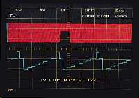 |
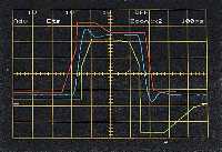
Demonstrating single line capture. This display shows the TV Triggering feature selecting a specific line. The top signal shows the complete frame while, using live Zoom, the lower signal shows the line in detail. The trigger system displays the TV line number, shown here as 177. |
|
The combination of very flexible triggering together with high speed transient capture and long |
 |
Updated 6 Jan 1997